Hi reader, and welcome in part 3 of the FNS series. In this blogpost I will show you how to create a Virtual Private Cloud with overlay network and a Load Balancer in FNS. My used lab is the same as in part 2 but I have added a couple (3) of webservers hosting a coloured website.
They are identical but the webpage has different colours 😉 I want those three virtual machines in their own VPC and a gateway Infront of them to be able to load balance those 3 webservers.
Virtual Private Cloud (VPC):
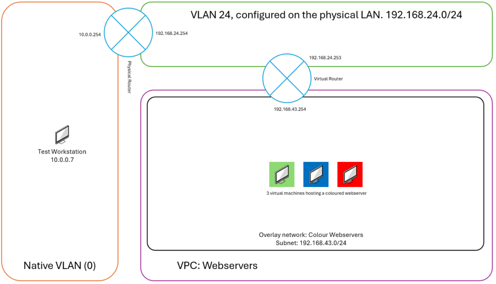
A VPC is a virtual network where different subnets can reside. This VPC is not configured on the switches or what so ever, it is only available on the Nutanix cluster. This simple drawing will explain a VPC:
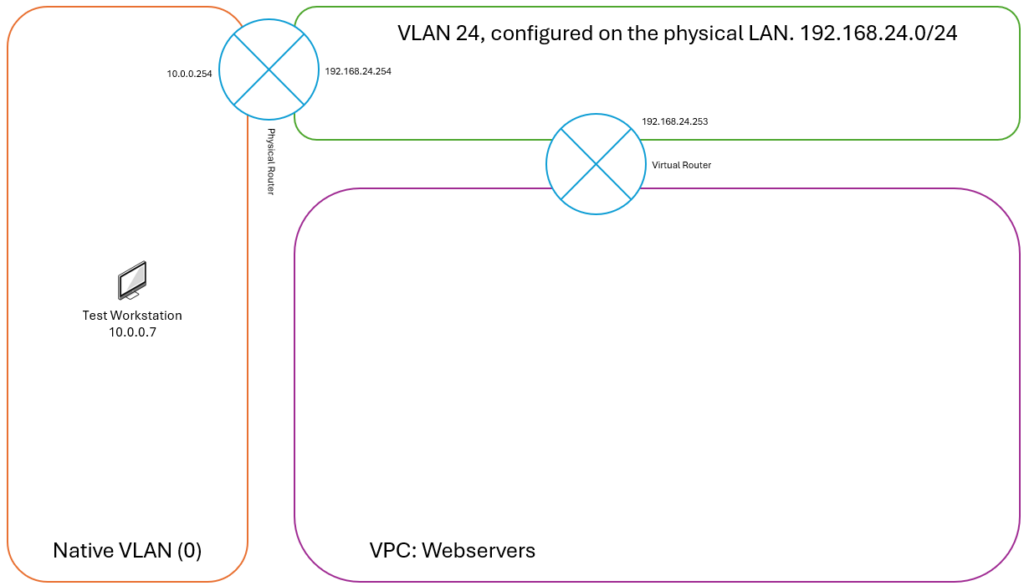
As you can see my setup is easy. I got a native vlan (0) and vlan 24 on my physical network. The purple VPC named WebServers is the VPC, witch will be connected via a virtual router, to VLAN 24. The VPC will only be available on the cluster. And has external connection via the virtual router. Lets make this:
First we start with creating a subnet. This will be VLAN 24 and will be used for external connections for VPC’s. Navigate to: Network & Security –> Subnets –> Create Subnet.
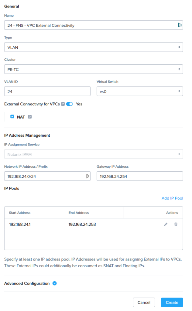
As you can see on the screenshot above the following settings are configured:
- Name: 24 – FNS – VPC External Connectivity
- This is my name I used to identify the subnet
- Type: VLAN
- Cluster: PE-TC
- This is my test cluster
- VLAN ID: 24
- This is the actual VLAN configured on you physical network
- External Connectivity for VPC: Yes
- Check NAT, as we will use NAT for incoming and outgoing traffic from the VPC. This make is easier to configure. When not using NAT you need to configure static routes in the netwerk to get the traffic correctly routed.
- IP Assignment Service: Nutanix IPAM
- Network IP Address / Prefix: 192.168.24.0/24
- This is the actual IP configuration for VLAN 24
- Gateway IP Address: 192.168.24.254
- VLAN 24 gateway
- IP Pools: 192.168.24.1 – 192.168.24.253
- In my case I just let this VLAN completely been managed by FNS. So there can be more VPC’s connected later on this specific VPC
When the subnet, with External VPC Connectivity, is created we can create the VPC named WebServers. Navigate to: Network & Security –> Virtual Private Clouds –> Create VPC.
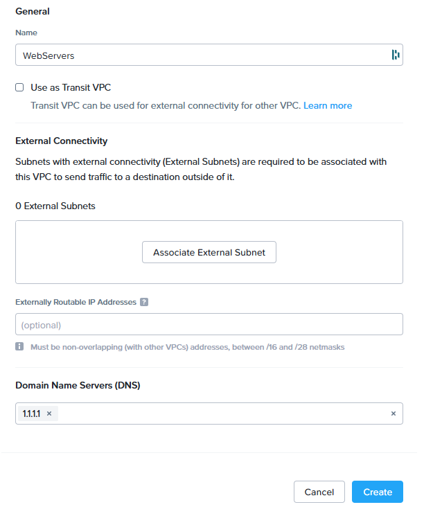
- Name: WebServers (as this will be a VPC to host all kind of webservers)
- Dont select transit VPC, this we are not going to use
- Domain Name Servers: 1.1.1.1
- This is the DNS server given to resources in the VPC
Click on “Associate External Subnet”
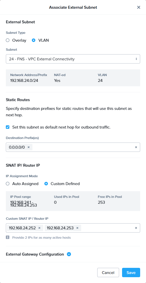
On this screen we are configuring the virtual router which resides in-between VLAN 24 and the VPC.
- Subnet Type: VLAN
- Select the VLAN with the external connectivity we created earlier
- Select: Set this subnet as default next hob for outbound traffic
- IP Assignment Mode: You can select Auto Assigned to let Nutanix self decide what the IP-Address will be, be we have decided to make it custom.
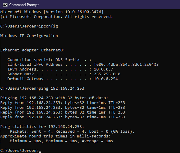
Now the VPC is created and we can ping the virtual router from the test workstation:
Overlay Network:
An overlay network is a virtual subnet in the VPC. In an overlay network you can place virtual machines and they will use the VPC virtual router to communicate outside the VPC:
In the drawing above you can see the overlay network named: Colour Webserver. This overlay network will use subnet 192.168.43.0/24 and the gateway for that subnet is 192.168.43.254. The 3 webservers will be placed in the overlay network and they will get the IP via DHCP. Let’s configure this.
Navigate to: Network & Security –> Subnets –> Create Subnet
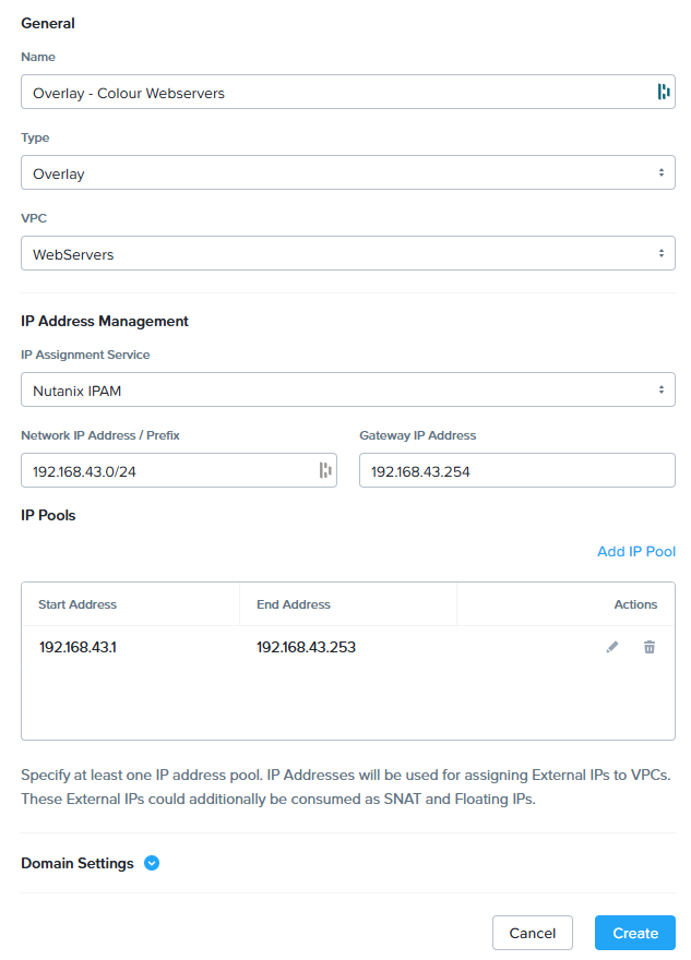
- Name: Overlay – Colour Webservers
- Type: Overlay
- VPC: WebServers
- IP Address Management: Nutanix IPAM
- Network IP Address / Prefix: 192.168.43.0/24
- This is the IP Config the virtual machines will use
- Gateway IP Address: 192.168.43.254
- This will be the virtual router IP address in the overlay network
- IP Pools: 192.168.43.1 – 192.168.43.253
- The DHCP scope in the overlay network
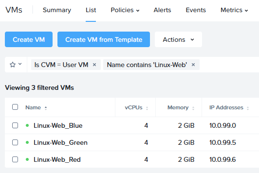
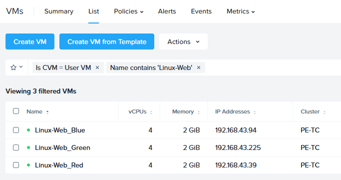
When the overlay network is created we need to attach the three webservers to it:
Now lets login to one of the virtual machine and see if external connectivity is possible:
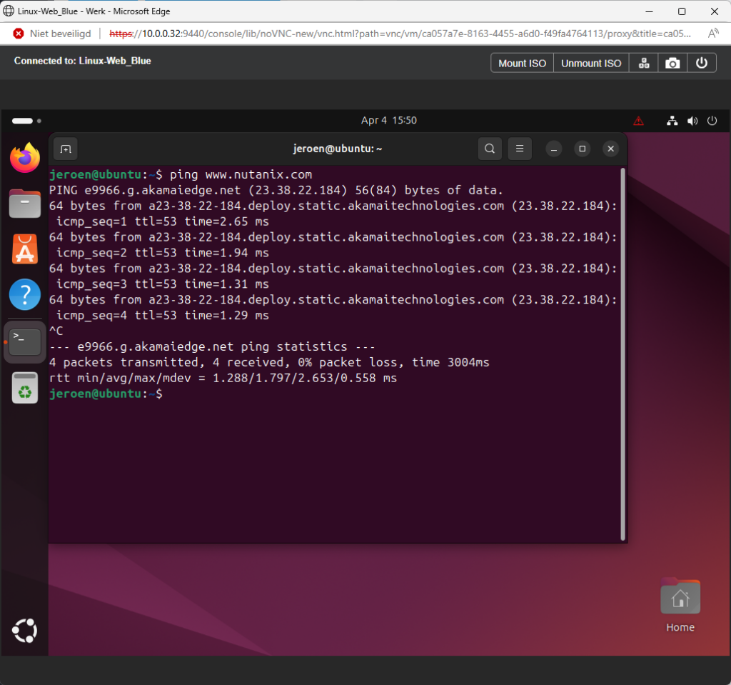
Nice, we have internet access via the virtual router using NAT.
Floating IP:
The next step is to create a floating IP in VLAN 24 – FNS – VPC External Connectivity. This IP will be used to access the webservers from outside the VPC. This IP address will be used to load balance the three (3) webservers.
Navigate to: Network & Security –> Floating IPs –> Request Floating IP.
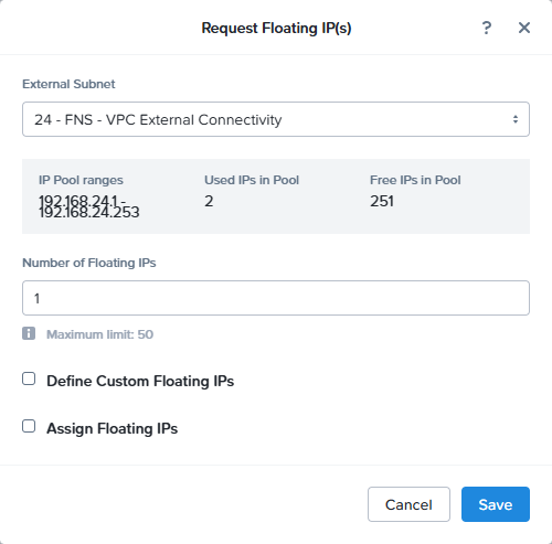
Just hit save and a floating IP is created:
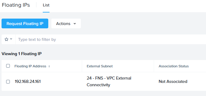
In my case: 192.168.24.161 will be the floating IP to be used.
Load Balancer:
Now it is time to create the load balancer to be able to access the three (3) webservers in a load balanced method. Navigate to: Network & Security –> Network Services –> Network Load Balancer –> Create Session.
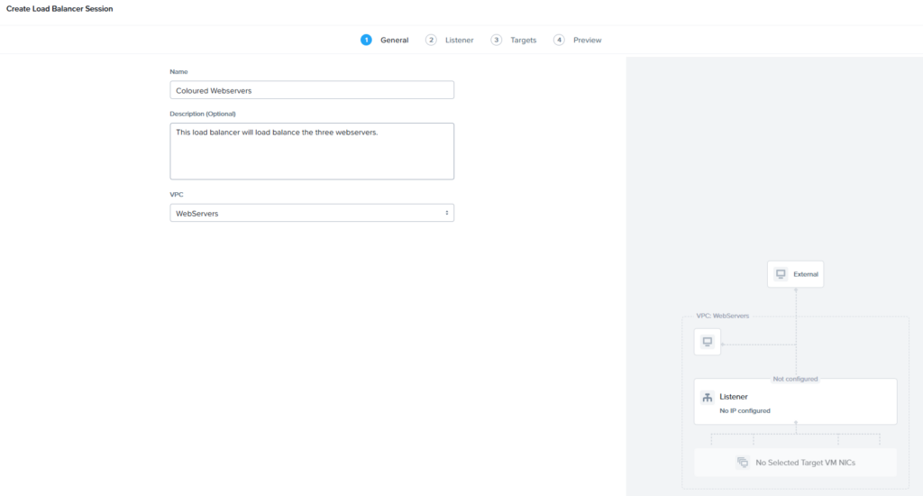
Give it a name (Coloured Webservers) and a description. Select the correct VPC: WebServers. On the next page we need to create the listener.
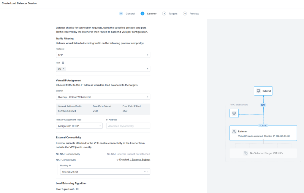
My webservers are hosting a webpage on TCP port 80. So the protocol and port can be filled in correctly.
In the “Virtual IP Assignment” we select the overlay network where the webservers are located. In my case: Overlay – Colour Webservers.
Primary Assignment Type: This is the IP address used for the load balancer in the overlay network. For the Citrix NetScaler readers, this is the subnet IP 😉 I will leave it on DHCP for easy configuration.
The last step is to select the floating IP: 192.168.24.161.
At the time of writing the only load balancing algorithm is “Five Tuple Hash”. Lets hope more options will be available later.
An the next screen we need to add the three webservers and set the correct listener port on their side:
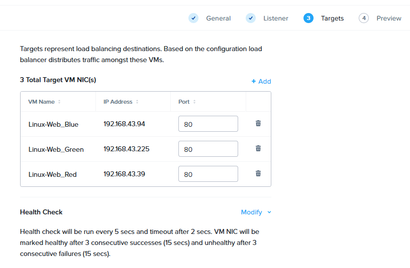
I’ve added the three webservers and changed the port from the default 8080 to 80 😉
Now the cool dynamic picture on the right side looks like this:
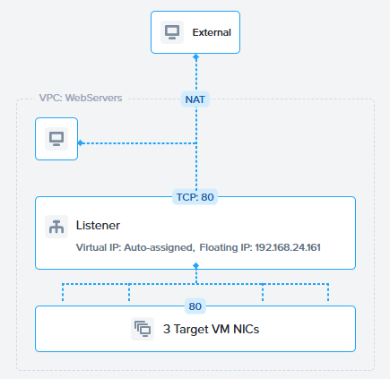
And yes, that is exactly what we wanted to create. Hit the next button and create the load balancer.
Now from my test workstation I’m going to access the load balancer via the floating ip: http://192.168.24.161
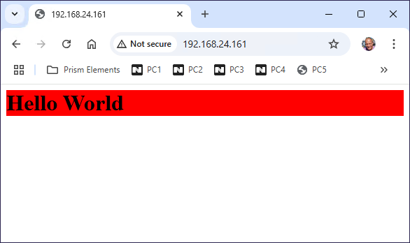
Pretty cool. From other workstations I will get one of the two other websites.